Rebuilding a Combination Transmission
Looking For Something?
Due to their usefulness by adding several more gear selections, the popularity and demand for Sherman combination transmissions remain high among Ford “N” tractor owners. This high demand has brought lots of Shermans out of the woodwork from salvage yards and individuals parting out tractors to sell the high demand parts. Unfortunately, this has been a mixed blessing as many of these transmissions have been sitting and rusting for long periods of time or they are badly worn. The Shermans were very well made and extremely durable, but they wear out just like the rest of the tractor. They’re 50-60 years old and it would be unreasonable to expect them to be in perfect condition without being rebuilt. It’s entirely possible to get a good used Sherman from a salvage yard or from eBay, but it’s also possible you’ll get a junker and lots of people have done just that. Statements from sellers like “I took the top off and all the gears look good” or “I drove the tractor and it shifted fine” are not nearly enough to assure you’re getting a good one. We’ve heard from dozens of people who have installed a used Sherman and then ask us what could be wrong with their bargain transmission when it pops out of gear, whines, growls, or doesn’t shift properly. That’s one of the reasons for the creation of this webpage, to help Sherman owners evaluate and repair their transmissions. Splitting the tractor to install a Sherman is too much work to have to do it all over again when the Sherman isn’t right.
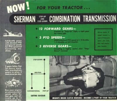
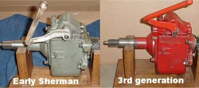
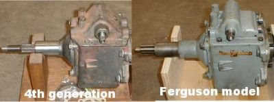
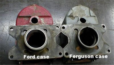
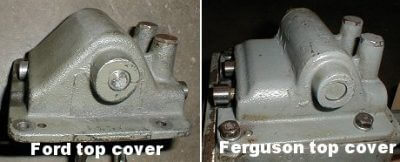
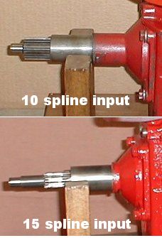
There are a few variations on the Sherman combination transmission but the internals are all basically the same. The early models were painted gray and the earliest of those had no retaining set screws for the input shaft bearing. The next generation was painted red but there were no other changes. The third generation had the casting extended on the top cover to completely enclose the shift rails with Welch plugs in the end of the rail bores. They also had a seal added in the top cover to the shifter shaft. These transmissions were for the 9N-2N-8N-NAA and 600 thru 900 series tractors. The fourth generation had the input shaft and nose cone changed to fit the 601 thru 901 series tractors. These tractors used a 15 spline clutch and the earlier tractors used a 10 spline clutch. In the late ’50’s the last generation of the Shermans was produced by Ford rather than Sherman for the “01” series and the 2000-4000 tractors thru 1964. These transmissions can be identified by the Ford part numbers cast into them rather than the Sherman part numbers. They were not painted at all. The rear oil slinger was changed to a ribbed type rather than the previous fan type and the shifter forks were cast steel rather than forged. However, all the parts of the latest transmissions were backward compatible so they would interchange directly with the earlier transmissions. The one other Sherman combination available was the model made specifically for the Ferguson TO-20 and TO-30. It was painted a lighter gray, had a modified lower case for clearance of the Ferguson countershaft cap and a modified top cover. The Ford Sherman will NOT fit a Ferguson tractor but the Ferguson model Sherman WILL fit a Ford.
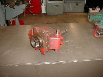
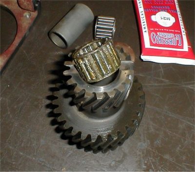
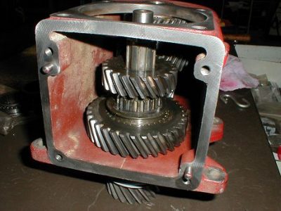
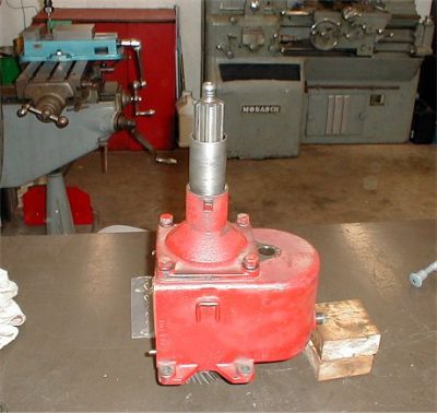
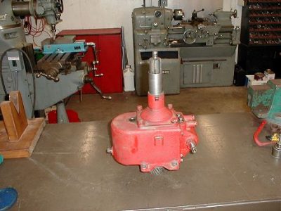
The Sherman combination being rebuilt in the following photos is a 2nd generation model. It was advertised as being “Very good condition, came from a running tractor, works great”.
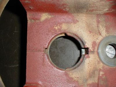
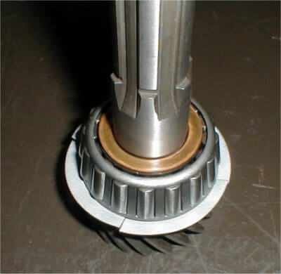
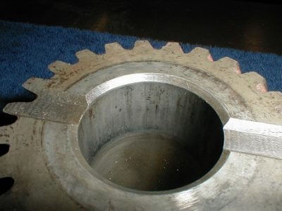
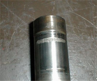
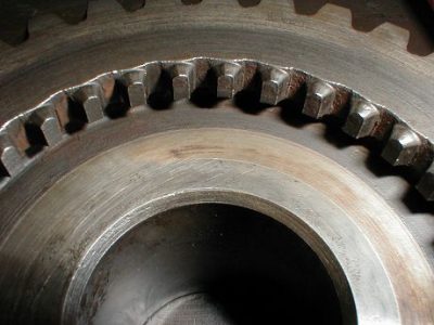
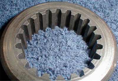
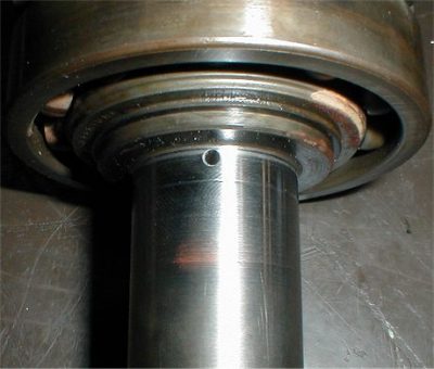
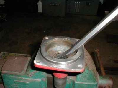
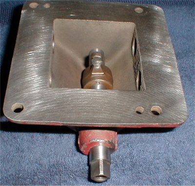
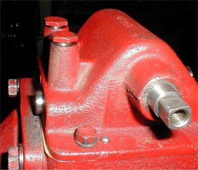
Before disassembly a quick look at the outside reveals major problems with the output shaft.
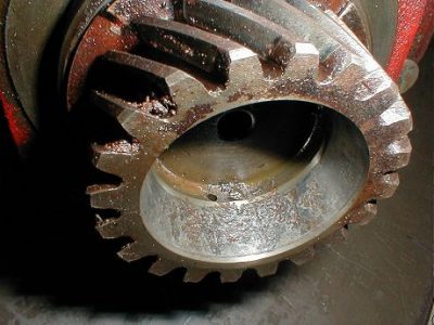
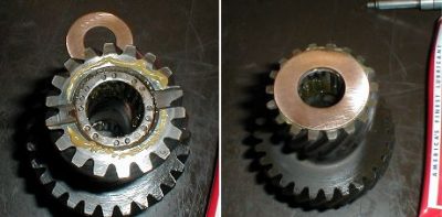
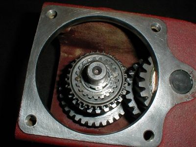
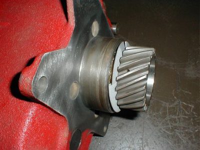
There is serious rust pitting in the back of the output gear. This area is actually the bearing cup or “race” for the front Timken bearing on the tractor’s mainshaft.
The bearing race surface must be smooth. Installing it like this will mean a growling noise and vibration that will soon destroy the bearing on the tractor’s mainshaft.
This pitted output shaft is junk and this has quickly become an expensive Sherman rebuild.
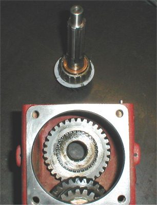
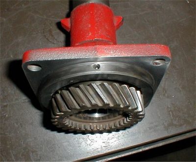
First we completely disassemble the Sherman. Disassembly is simple and straightforward. Remove 4 bolts and remove the top cover, remove 4 bolts and remove the front input shaft and nose cone, remove the snap ring and take out the rear shaft and gears, drive the lower shaft out the rear of the case and remove the cluster gear.
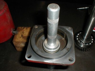
When removing the input shaft from the nose cone be sure to back off the 3 setscrews (shown above) that keep the bearing in place before separating those two pieces.
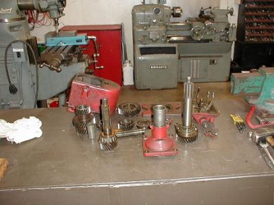
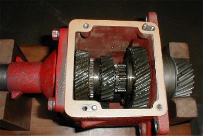
It takes only a few minutes to have the Sherman all apart. Here it’s disassembled and ready for a solvent bath.
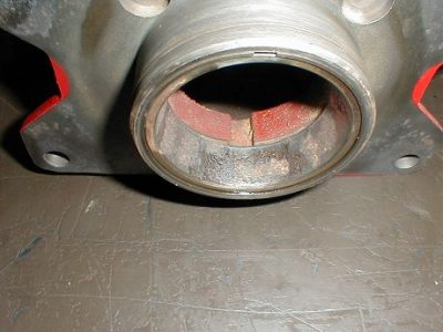
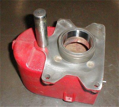
Starting with the main case we find the output shaft bearing race (cup) is badly rusted and needs replaced.
The 2 notches on the inside of the case will let you use a punch to knock the old bearing race out.
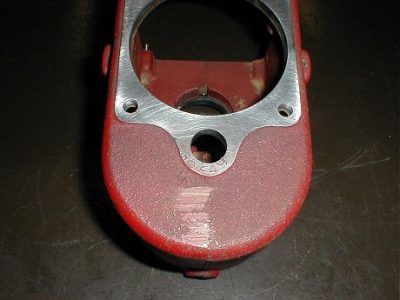
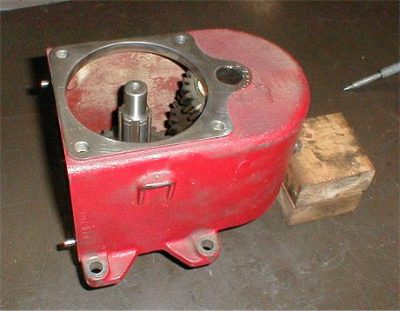
Clean and inspect the case for any cracks or other flaws. All the Sherman combinations have their serial numbers on the front of the case below the countershaft bore.
The earliest number we’ve seen was in the 3000 range and the latest on a Ford case was in the 75000 range. This one is serial number 36249.
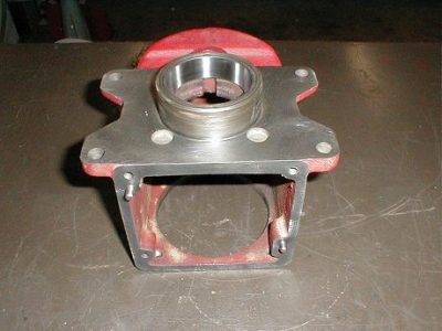
The case has been cleaned, inspected, and a new bearing race installed.
Next we remove the old bearing and oil slinger from the output shaft.
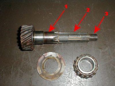
If the rear bearing cup on the output shaft was ok we’d need to check out the rest of the shaft. Diameter #1 is where the step-down gear rides on the shaft.
There should be no wear or scoring on this surface. If there is a problem here there will also be a problem in the bore on the step-down gear.
Diameter #2 on the splines is where the step-up gear rides on the shaft. Wear here is fairly common and it’s not good. A couple of thousandths wear is ok but any more requires a new shaft.
Wear here also indicates there is likely a problem in the bore of the step-up gear. The step-up gear can become rippled inside and will also need to be replaced.
Diameter #3 is the inside shaft for the needle bearing on the main shaft. It should have no wear or pitting. If it does, the needle bearing won’t last long.
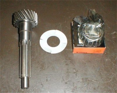
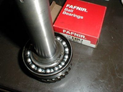
The new output shaft, slinger and bearing ready to assemble.
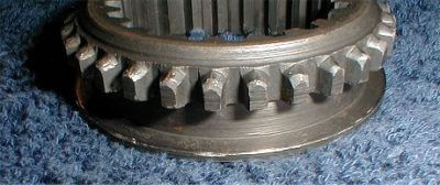
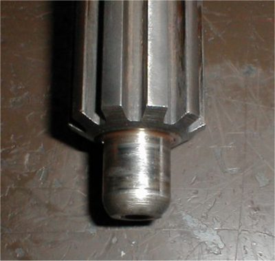
The bearing cup end of the output shaft should look like this or close to it.
Very minor pitting can be acceptable if the pits are small enough that none of them span the length of a roller on the bearing. If there is any pit or flaw big enough that a roller can be affected by it, the bearing will be noisy and will soon fail. That could mean big trouble.
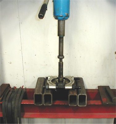
Pressing the new bearing onto the shaft. The slinger should be tightly locked under the bearing when you’re done.
Drop on the rear thrust washer and the output shaft is ready to install. This washer should be .062-.065″ thick.
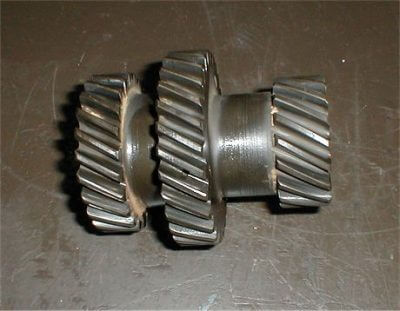
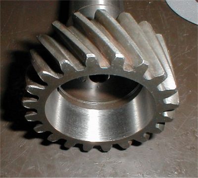
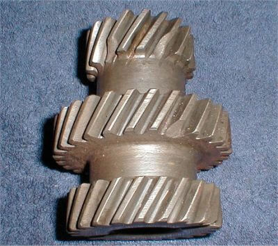
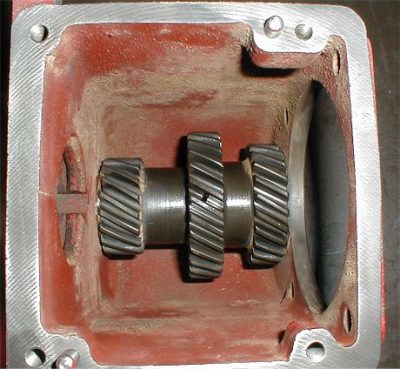
Next, closely inspect the lower cluster gear. All the gear teeth should be in good shape with no abnormal wear. Fortunately, the cluster gear in this transmission is a good one.
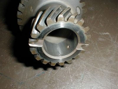
The needle bearings for the countershaft run directly against the inside bores of the cluster. Inspect the bore on each end for any pitting or damage to the bearing surface.
It should be smooth and free of pitting or any other flaws, just like this one. A rough surface here will cause growling noises and will soon destroy the lower bearings.
This is an example of a cluster gear that has 3 chipped teeth. It’s junk. Chipped teeth on the cluster gear cannot normally be seen just by removing the top cover on the transmission. This is the type of hidden damge you do not want to find. when you disassemble your Sherman.
The bearing bores in this example cluster gear show some pitting along the length of the needle bearing area and some galling near the inside end. This is not good.
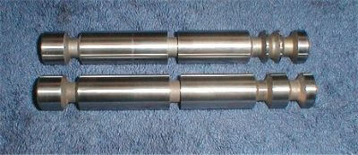
Many times when there is wear on the countershaft and/or cluster gear bearing diameters the bearings will come out in pieces. Note the galling on this countershaft front bearing diameter. This shaft is junk.
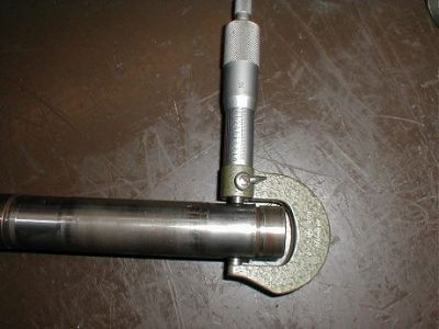
Measure the countershaft at the bearing diameters. It should be smooth and round and should be 1.000″ in diameter. If the shaft is otherwise in good shape I will accept a size of .997″ but no more than that. If it’s worn too much the transmission will be noisy and the bearings will fail.
This one is badly worn and measures .984″. It’s junk.
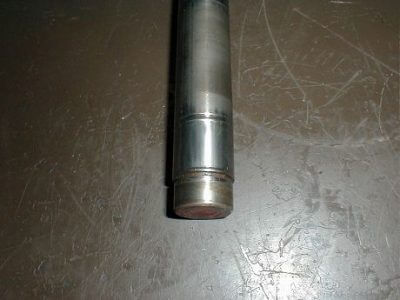
An example of a badly worn countershaft bearing diameter.
An example of galling on the rear end of a countershaft bearing diameter. More junk.
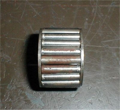
This needle bearing has rust and pitting on the rollers. The rollers are also starting to crumble on the left end. It’s very rare to find any of these that are good enough to use over again. Replace ’em.
If the countershaft is good with no excessive wear or pitting it can and should be lightly polished before reinstalling.
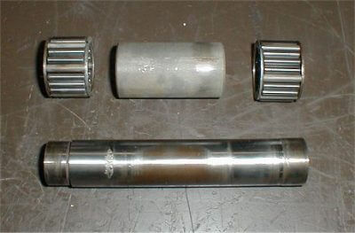
The countershaft with bearings and thrust washers ready to install.
Install the 2 bearings and the center spacer into the cluster gear. Apply a good coating of assembly grease to all parts when installing.
“Gluing” the thrust washers to the cluster gear with assembly grease will keep the bearings inside in place while you put the cluster assembly into the case. The small gear goes toward the rear of the case. Note – the front and rear end thrust washers are different. The one with the smaller hole goes on the front end.
Be sure to have everything lined up as the countershaft goes in. The last 1/2″ or so is a press fit.
Once the cluster gear is installed make sure it turns freely and check end play with a feeler gauge. It should be at least .005″ and no more than .025″. If it has too much end play you need new thrust washers.
Next, closely inspect the step-down gear. Make sure there are no chips or abnormal wear on the gear teeth and no wear or rough spots in the bore. Since this gear spins with a metal to metal contact on the output shaft it must be a good fit and have a smooth surface inside the bore.
Then check the dentals on the front side where the sliding collar engages with the step-down gear. They should look just like the ones in this photo. Any abnormal wear or damage to the dentals will result in a transmission that jumps out of gear under a load.
See the photos below of the sliding collars for examples of abnormal wear on the dentals.
Put assembly grease on the output shaft tapered bearing and thrust washer and in the bearing cup on the back of the case. Grease the bore on the step-down gear and place it into the case as shown.
Lower the case with the step-down gear down over the output shaft and use a wood block or other suitable item to support the bottom end so it sits flat on the bench as shown.
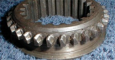
Next is the extremely important inspection of the sliding collars. The sliding collars must be in good shape or the Sherman will not stay in gear.
While the two sliding collars may look alike at first glance, they are not alike. Don’t mix them up when assembling. The dentals on the collar in this photo are chipped on the ends, probably from someone trying to shift gears without stopping the tractor first.
The sides of the dentals still look pretty good. While it’s not the best, one like this would probably work ok if you can’t locate a better one.
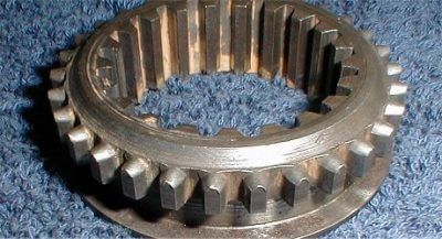
The dentals on this collar are badly worn and came from a transmission that would not stay in gear. You can easily see why. This collar is junk along with the step-down gear it mated with.
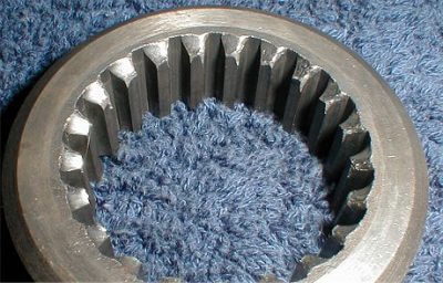
The dentals on the outside of this collar are excellent, just like new. We’ll use this one.
The rear sliding collar (hi/lo) engages the step-down gear on the outside dentals and engages the step-up gear on the inside of the opposite end. This collar shows badly worn inside splines. It’s junk, as is the step-up gear it mated with.
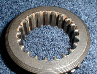
A good one looks like this which shows almost no wear and is nearly perfect. We’ll use this one.
The front sliding collar (direct) has no dental chamfers on the inside splines because it only mates to the front input shaft with the external dentals.
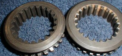
A glance at the inside splines will tell you which collar is which. The one on the right is the rear hi/lo collar.
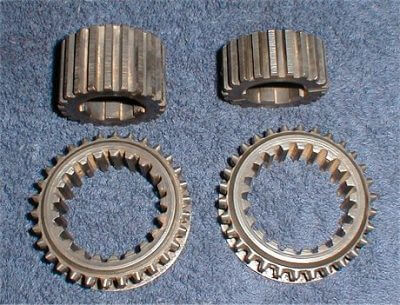
The hubs for the sliding collars are also different. The longer hub is for the rear collar and the shorter one is for the front collar.
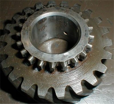
Next we inspect the step-up gear. The dentals should look like these which are in excellent condition.
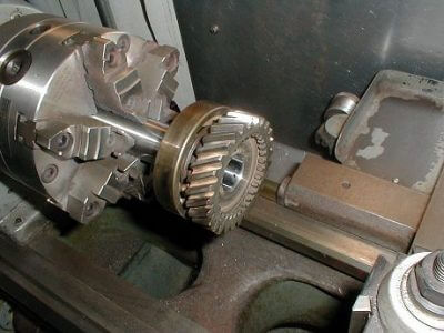
The bore should be smooth and round and be a good fit to the output shaft. This bore is very good but has a couple of tiny rust pits.
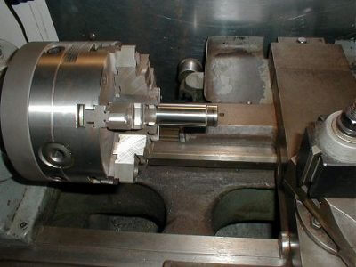
We will chuck it up in the lathe and polish it lightly with a fine emery paper before installing it.
Place the longer hub and the rear sliding collar over the output shaft in the case.
Next, install the step-up gear onto the shaft, dentals to the rear. You should be able to slide the collar freely between the step-down and step-up gears and engage either one.
Install the front hub and collar and install the snap ring to keep it all in place.
Install the brass washer and a new needle bearing and we’re ready for the front input (clutch) shaft.
The front end of the clutch shaft is supported by the pilot bearing in the flywheel.
If the pilot bearing goes bad it can wear the bearing diameter badly on the input shaft and you’ll need to replace the input shaft or repair the bearing diameter.
This one shows signs that it has spun inside the pilot bearing at some time or other but it has no measurable wear and will be just fine.
Check the clutch splines for wear also. The clutch splines on this one look like new.
Next, check the seal diameter on the shaft. It should have no measurable grooves or wear. If it does, the seal will never be able to keep the oil in. This one has just a very slight line where the seal rides. It’s good.
Check the dentals closely on the inside rear of the input shaft gear just like we did for the dentals on the step-down gear.
These dentals engage with the front sliding collar for the direct range on the Sherman. Also inspect the bore in the back of the gear.
The mainshaft needle bearing rides in this bore and it has to be good. Here we’ve lightly polished the bore to remove some rust staining.
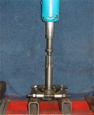
Remove the snap ring and press the old bearing off the input shaft if it needs replaced (they nearly always should be replaced).
Press the new bearing on and replace the snap ring. Always use the heavy duty version of the bearing here and not the standard duty. The heavy duty bearing has more balls to carry the heavy radial load from the input shaft.
Remove the old seal from the nose cone with an inside puller or a pry bar.
Install the new seal with a suitable driver. The seal lip goes toward the inside of the case.
Install the input shaft into the front nose cone. Make sure the bearing seats all the way into the pocket.
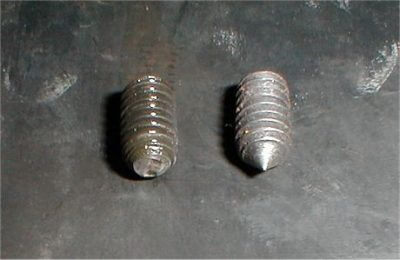
Install the 3 set screws that keep the bearing in place in the nose cone. Inspect them to be sure the cone point is still intact like the one on the right in this photo.
If the point is sheared off like the one on the left the set screw needs replaced. The point is the only thing that holds the bearing in place as it protrudes just above the outer bearing race.
Do not tighten these set screws more than “snug” as you can distort the bearing race and cause premature bearing failure by over tightening.
Put a new gasket on the flange and install the nose cone and input shaft onto the case.
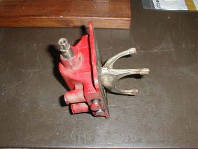
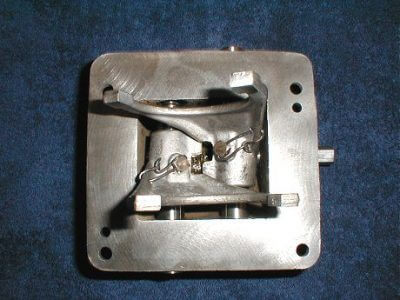
That finishes the main Sherman gearbox which brings us to the top shifter cover. The top cover needs to be completely disassembled and checked over closely. Lots of shifting problems are caused by simple problems in the top cover.
To disassemble the top cover, remove the 2 tower caps and remove the detent springs and balls.
The shift rails should now move freely. Cut the safety wires from the set screws in the forks and remove the set screws.
The shifter rails will now come out either end and the forks can be removed. Remove the snap ring on the shifter shaft and pull the shaft out of the shift finger and out of the case.
Remove the set screw on the side of the cover and slide the interlock pin out.
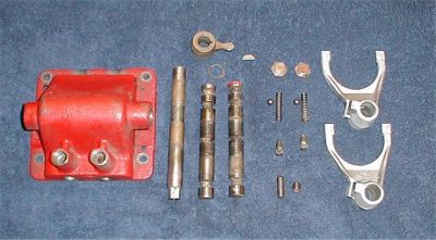
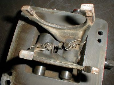
The disassembled top cover and all the parts.
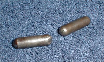
Check the interlock pin. Both ends should be round like half a ball and smooth, not gouged or sheared like the one on the left in this photo.
If it’s bad, replace it. This pin is what keeps the transmission from going into 2 gears at once. When you shift one rail, the pin slides over and locks the other rail in the neutral position.
Lubricate it with some 90w gear lube and install it back in it’s bore, making sure it slides freely from side to side.
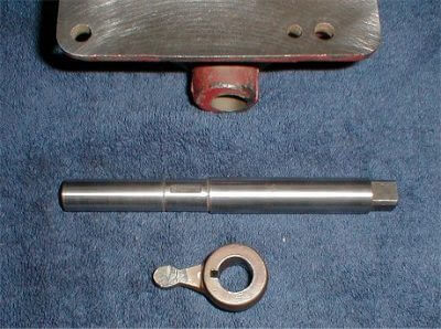
The shifter shaft should be polished and checked for straightness. Make sure the Woodruff key slot and the snap ring grooves are good. Check the shift finger for cracks, straightness and excessive wear on the business end.
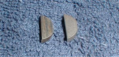
Replace the Woodruff key. The key always wears on the sides and a little bit of wear on the key translates to a lot of play at the end of the shifter lever.
Install the shifter shaft, key, shifter finger and snap ring back into the top cover.
Make sure the shifter shaft moves freely back and forth and rotates freely side to side.
Lube everything with 90w gear lube when assembling. Removing and installing the snap ring is easier with a set of snap ring pliers with a 45 degree bent nose.
The two types of shift rails are shown here. On top is the later rail that has a detent for the neutral position (a nice addition).
The lower one is the early style. Polish the rails and inspect for straightness and any damage such as rust pitting, scoring or galling. Watch for grooves from the detent ball wearing into the rail.
Slide both rails into the top cover and make sure they work freely back and forth and rotate without any binding or tight spots which could indicate a bent rail.
Remember the single groove end of the rail is for the interlock pin and the 2 or 3 groove end is installed under the detent ball towers.
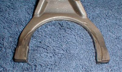
Inspect the shifter forks for cracks, straightness and wear. The fork above is badly worn. It’s junk. Do not try to use something that looks like this one in your Sherman.
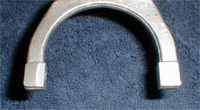
This is a forged steel fork used in the earlier Shermans. It’s in very good condition with only the slightest sign of wear.
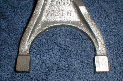
This is a later style cast steel fork from a Ford built Sherman. They are interchangeable with the early style. This one is also in excellent condition with almost no wear at all.
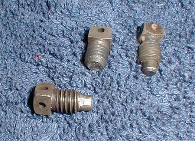
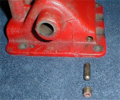
This is the dog point set screw that keeps the shifter fork lined up with the small groove in the center of the shift rail.
It’s this little guy that causes a lot of shifting problems. Only the shear strength of the dog point on the set screw keeps things aligned and they can shear off as you can see on the one in this photo.
Make sure the dog point is good, not worn on the sides or bent or broken.
Replace with new ones if there is any doubt. If one of these dog points shears off, the shifter fork will move with the lever but the rail will not and the interlock will effectively block your other gear range until you replace the set screw.
The one on the right is good.
Place the shifter forks into the cover, slide the rails into the forks, align the center groove in the rail with the set screw holes, and install the set screws finger tight.
Turn the set screws until snug then back them off slightly until the fork moves freely side to side without the rail rotating.
The fork must be retained to the rail by the dog point only and not by pressure from the screw. Do NOT tighten the set screws with a wrench.
Once the set screws are where they belong use safety wire to keep them in place. You should now be able to shift the forks through the 3 different gear positions and everything should move smoothly and easily.
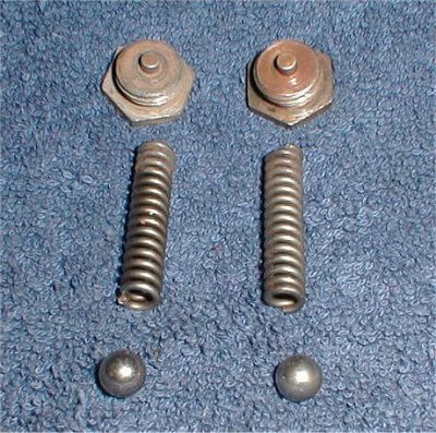
Inspect the detent springs for breakage or mushrooming on the ends and replace them if needed.
The detent balls get rusty and develop flat spots. Always replace them – they only cost a few cents each.
Be sure to lube the detent tower bores and the balls and springs with 90w gear lube when you install them.
Everything in the gearbox should have a light coating of assembly lube.
Install the new gasket and the top cover. Be sure to get the shifter forks lined up with the grooves in each sliding collar and lower the top cover into place.
Leaving the detent caps a little loose will make it easier to shift the transmission while you are bench checking. Don’t forget to tighten them when you’re done.
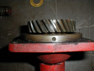
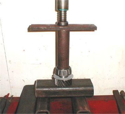
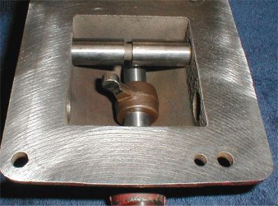
When the Sherman is installed in the tractor the output shaft is held secure because it’s loaded against the tractor transmission main shaft.
Do not try to shift the Sherman before it’s installed without putting some pressure on the output shaft end.
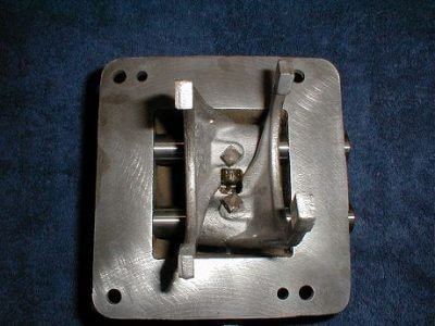
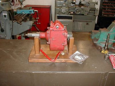
For testing, place the output shaft end of the Sherman down on the workbench so the weight will help keep the output shaft in place when you shift it.
In this position you can shift gears and turn the Sherman case around while observing the input shaft.
In the high range the input shaft will appear to turn faster than you are turning the case.
In low range the input shaft will appear to turn backwards from the direction you’re turning the case, and in direct range the input shaft will not move at all while you turn the case.
With the output shaft held in place be sure the oil slinger is not rubbing on the case. It can be gently “adjusted” for clearance if necessary.
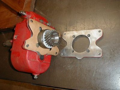
The last item is a new gasket for the mounting plate surface. Make this gasket from 1/64″ gasket material. Be sure to check the mounting plate for flatness and for cracked or stripped threads.
All finished. Once you’ve refurbished your Sherman in this manner, have it installed with the correct shims for bearing load, and have it filled with fresh gear oil, you can rest assured it will shift correctly, run smoothly and quietly, and provide reliable service for another 50 years.
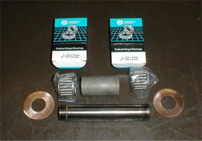
Bearings used in the Sherman combination transmission –
- Input shaft bearing – ND 3210
- Mainshaft needle bearing – Hyatt 93316
- Output shaft cup – Timken 25820
- Output shaft cone – Timken 25877
- Countershaft bearings – Hyatt 93516
- Late style top cover shifter shaft seal C/R 6720
Other parts available from New Holland dealers –
- Front seal 8N7052A
- Front nose gasket C0NN7C251B
- Top cover gasket C0NN7223D
- Shifter fork C0NN7231B
- Shifter fork setscrew C0NN7B360A
- Output shaft C3NN7015D
- Cluster gear C0NN7113B
- Front countershaft thrust washer C0NN7119A
- Step-up gear C0NN7A062A
- Front sliding collar C0NN7A061A
- Detent spring C0NN7C349A
- Detent ball 72387
- Most other parts are no longer available new and must be located used.
Thanks to John Smith of Old Ford Tractor for allowing us to use this information.